Delays are an essential part of electronics such that a set of instructions can be executed in a specific order. There are two main categories of delays: critical and non-critical. Critical delays are delays associated with systems that require high accuracy, such as an MCU’s crystal oscillator operating at 32 MHz, which oscillates with a period of 31.125 ns, i.e., a HIGH delay period of 15.625 ns and a LOW delay period of 15.625 ns. Non-critical delays are delays associated with systems that do not require high accuracy, such as switching an LED ON for a HIGH delay period of 1000 ms, followed by switching the LED OFF for a LOW delay period of 1000 ms. Another method of establishing a non-critical delay is to use a Resistor-Capacitor (RC) delay circuit, as shown in Figure 1.

There are four fundamental elements: power source (VDD), resistor (R), capacitor (C), and output voltage (VCAP). Before the VDD voltage is applied to the RC circuit, the capacitor’s voltage remains at 0 V, assuming it is fully discharged. Equation 1 describes the voltage across a capacitor in an RC delay circuit, whilst Equation 2 represents the time constant (𝜏).
\begin{equation}
\tag{1}
V_{CAP}{(t)}= V_{DD}(1-e^{-\frac{t}{{𝜏}}})
\end{equation}
\begin{equation}
\tag{2}
𝜏= RC
\end{equation}
At one time constant, i.e., t = 𝜏, the voltage across the capacitor is approximately 63.2% of the supply voltage (VDD), as shown in Equation 3.
\begin{equation}
\tag{3}
V_{CAP}{(t)} = V_{DD}(1-e^{-1})\approx 0.632 V_{DD}
\end{equation}
The time constant is therefore the time it takes for a capacitor to reach a charge of 63.2% of the supply voltage. The rise time is the time it takes for the capacitor to charge from 10% to 90% of the supply voltage. There are a couple of reasons why the rise time is not taken from 0% to 100% of VDD. The first reason is because as soon as the power supply is switched ON, the initial voltage may contain noise. The second reason is due to the fact that a capacitor can never be charged to VDD due to its exponential charging nature; hence, 90% of VDD is “close enough”. Figure 2 represents the charging profiles for three different capacitors: 4.7 μF, 47 μF, and 470 μF.
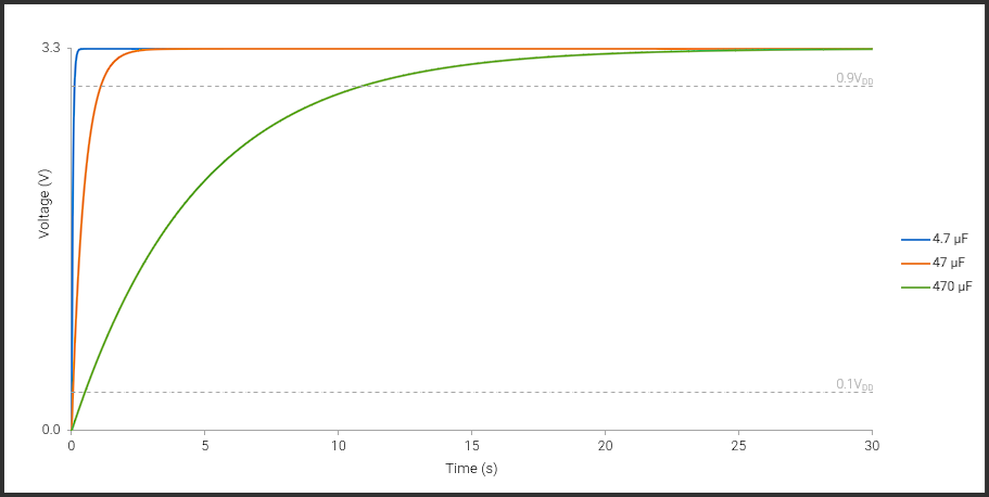
The capacitor with the smallest capacitance appears to charge the fastest, whilst the capacitor with the largest capacitance appears to charge the slowest. The rise time for the 4.7 μF capacitor appears to be approximately 0.125 s. The rise time for the 470 μF capacitor appears to be approximately 1 s. The rise time for the 470 μF capacitor appears to be approximately 12 s.