The WT32C3-S5 is a WiFi module developed by Wireless-Tag Technology Co., Ltd., enabling connectivity between embedded systems and the IoT, utilising the ESP32-C3 WiFi chip, which was developed by Espressif. Third-party developers, such as Wireless-Tag Technology Co., Ltd., develop various PCBs, each with specific electronic components such as an indicator LED, tactile buttons, a USB port, an antenna port, etc., in addition to an ESP chip. Modules that have a USB port enable downloading/flashing of firmware onto the ESP, requiring no additional components. The WT32C3-S5, on the other hand, requires additional electronic components, such as that shown in the IoT Laboratory. Table 1 lists the operating modes of the WT32C3-S5 and its associated UART ports and functions.
| Mode | GPIO9 | UART Port | Pin | Function | ||
| # | Name | |||||
| Download | LOW | UART0 | 21 | GPIO20 (RXD0) | Download firmware | |
| 22 | GPIO21 (TXD0) | Output log | ||||
| Command | HIGH | UART1 | 7 | GPIO6 (RXD1) | AT command | |
| 16 | GPIO7 (TXD1) | Response | ||||
The UART0 port is used for downloading and logging data, while the state of GPIO9 is LOW. The UART1 port is used for receiving AT commands and sending responses accordingly, while the state of GPIO9 is HIGH.
To set up an IoT system that utilises the ESP32-C3, a number of steps need to be taken:
- Download firmware onto the ESP32-C3
- Send AT commands to the ESP32-C3 to configure operating characteristics
- Setup a Dynamic Domain Name System (DDNS) to maintain a connection with a router
- Enable port forwarding in a router to allow incoming traffic to the ESP32-C3
- Communicate remotely
Download Firmware
Video 1 demonstrates how to download AT firmware (factory) onto the ESP32-C3.
Table 2 lists various timestamps with a description.
| Timestamp | Description |
| Preparation | Download and open the latest version of the Espressif Flash Tool as the administrator. Ensure that slide switch (S1) is switched ON (GPIO9: LOW) to enable download mode. Download the ESP32-C3-MINI-1 firmware from the Espressif website. |
| 0:07 | The ChipType is ESP32-C3, the WorkMode is Develop, and the LoadMode is UART. Click “OK”. |
| 0:20 | Ensure that the correct COM port for the USB to RS232 cable and BAUD rate (115200 bps) are selected, then click “ERASE.” This will erase the current firmware on the ESP32-C3. Note that for most of these Wi-Fi modules, the default BAUD rate is 115200 bps. Dots may start appearing on the prompt (black screen). Press and release the tactile switch (SW1) to initiate a reset, which in turn will initiate the erase cycle. Once the erase cycle is complete, click “STOP.” |
| 0:46 | Click “START” to start reading the details of the ESP32-C3, which will be listed under “DetectedInfo.” Once the detected information is displayed, click “STOP.” |
| 1:02 | Enter the memory address 0x0 followed by selecting the firmware binary file (factory_MINI-1.bin). Ensure that the corresponding checkbox is checked. |
| 1:19 | Click “START” to start downloading. Wait some time for the progress bar to complete with a “FINISH.” Close the tool and ensure that slide switch (S1) is switched OFF (GPIO9: HIGH) to enable command mode. |
| 1:47 | Run MikroC Pro or a serial terminal software as the administrator. Set the correct COM port and BAUD rate (115200 bps). |
| 2:05 | Click “Connect” and press and release the tactile switch (SW1). If the message “waiting for download” appears in the “Receive” window, this indicates that the slide switch (S1) is tying the GPIO9 pin of the ESP32-C3 to GND. Set S1 such that the GPIO9 pin is pulled to VCC via the pull-up resistor. Press and release the tactile switch (SW1). |
| 2:22 | The “Receive” window displays a “ready” prompt at the bottom, indicating that the ESP32-C3 is ready to receive commands. |
| 2:25 | Within the Send window, send “AT” while enabling the “Append New Line” (carriage return + line feed) (\r\n) or a 13 followed by a 10. If received successfully, the ESP32-C3 will respond with an “OK,” indicating that “AT” commands can be sent. |
| 2:32 | Send “AT+GMR.” If received successfully, the ESP32-C3 will respond with the version of the firmware that was uploaded. |
For further details regarding downloading firmware onto the ESP32-C3 and sending AT commands, refer to the ESP32-C3 User Guide.
AT Commands
Table 3 lists AT commands that can be use to configure the ESP32-C3 to communicate, remotely, via the internet.
| Command | Parameters | Description | |||
| Test AT Startup AT | – | – | |||
| Check Version Information AT+GMR | – | – | |||
| Bluetooth Low Energy (BLE) Initialisation AT+BLEINIT | <init> | 0 | Deinitialise BLE | ||
| 1 | Client role | ||||
| 2 | Server role | ||||
| =0 | Example | ||||
| Set RF TX Power AT+RFPOWER | <wifi_power> | x * 0.25 dBm | WiFi power determined by variable (x) | ||
| <ble_adv_power> | 0: -27 dBm | RF TX Power of BLE advertising (If using BLE, set AT+BLEINIT to 1 or 2) | |||
| 1: -24 dBm | |||||
| 2: -21 dBm | |||||
| 3: -18 dBm | |||||
| 4: -15 dBm | |||||
| 5: -12 dBm | |||||
| 6: -9 dBm | |||||
| 7: -6 dBm | |||||
| 8: -3 dBm | |||||
| 9: -0 dBm | |||||
| 10: 3 dBm | |||||
| 11: 6 dBm | |||||
| 12: 9 dBm | |||||
| 13: 12 dBm | |||||
| 14: 15 dBm | |||||
| 15: 18 dBm | |||||
| <ble_scan_power> | Same parameters as <ble_adv_power> | ||||
| <ble_conn_power> | Same parameters as <ble_adv_power> | ||||
| =78 | Example | ||||
| Set WiFi Country Code AT+CWCOUNTRY | <country_policy> | 0 | Country code same as AP | ||
| 1 | Country code no change (code set by command) | ||||
| <country_code> | Country code maximum 3 characters | ||||
| <start_channel> | Channel number to start (1 – 14) | ||||
| <total_channel_count> | Total number of channels | ||||
| =1,”AU”,1,131 | Example | ||||
| Set WiFi Mode AT+CWMODE | <mode> | 0 | Null mode (WiFi disabled) | ||
| 1 | Station mode | ||||
| 2 | SoftAP mode | ||||
| 3 | SoftAP + Station mode | ||||
| <auto_connect> | 0 | ESP32-C3 not automatically connect to an AP | |||
| 1 | ESP32-C3 automatically connects to an AP | ||||
| =1,0 | Example | ||||
| WiFi Protected Setup (WPS) AT+WPS | <enable> | 1 | Enable WPS | ||
| 0 | Disable WPS | ||||
| <auth floor> | 0 | Open (default) | |||
| 1 | WEP | ||||
| 2 | WPA_PSK | ||||
| 3 | WPA2_PSK | ||||
| 4 | WPA_WPA2_PSK | ||||
| 5 | WPA2_ENTERPRISE | ||||
| 6 | WPA3_PSK | ||||
| 7 | WPA2_WPA3_PSK | ||||
| =1,7 | Example | ||||
| Set hostname of ESP32-C3 Station AT+CWHOSTNAME | <hostname> | Hostname of ESP32-C3 Station (max. length 32 bytes) | |||
| =”ESP32-C3″ | Example | ||||
| Automatically Connect to AP AT+CWAUTOCONN | <enable> | 1 | Enable automatic connection to AP when powered on (default) | ||
| 0 | Disable automatic connection to AP when powered on | ||||
| =0 | Example | ||||
| List Available APs AT+CWLAP | – | – | |||
| Connect to AP AT+CWJAP | <ssid> | SSID of AP | |||
| <pwd> | Password (64 characters MAX) | ||||
| <bssid> | MAC address of AP | ||||
| <pci_en> | 0 | Connect using encryption methods (including OPEN and WEP) | |||
| 1 | Connect using encryption methods (not including OPEN and WEP) | ||||
| <reconn_interval> | 0 | ESP will not reconnect to AP when disconnected | |||
| 1 – 7200 | ESP will reconnect to AP at specified interval when disconnected (default 1) | ||||
| <listen_interval> | 1 – 100 | Interval of listening to AP’s beacon (default 3) | |||
| <scan_mode> | 0 | Fast scan to connect to first AP (ends after AP is found) | |||
| 1 | All channel scan to connect to AP with strongest signal (ends after all channels are scanned) | ||||
| <jap_timeout> | 3 – 600 | Maximum timeout for this command (default 15) | |||
| <pmf> | 0 | Connect to APs that do not require PMF | |||
| 1 | Connect to APs that require PMF | ||||
| =”SSID”,”Password” | Example | ||||
| Query WiFi State and Information AT+CWSTATE? | – | – | |||
| Set IP Address of ESP32-C3 Station AT+CIPSTA | <“ip”> | IPv4 address of ESP32-C3 Station | |||
| <“gateway”> | IPv4 address of router | ||||
| <“netmask”> | |||||
| <“ipv6 addr”> | |||||
| =”192.168.0.12″,”192.168.0.1″,”255.255.255.0″ | Example | ||||
| Obtain Local IP and MAC Address AT+CIFSR | – | – | |||
Multiple Connections AT+CIPMUX | <mode> | 0 | Single connection | ||
| 1 | Multiple connections | ||||
| =1 | Example | ||||
| TCP/SSL Server AT+CIPSERVER | <mode> | 0 | Delete server | ||
| 1 | Create server (AT+CIPMUX = 1) | ||||
| <param2> | <mode> = 1 | Port number (0 – 65,535) (default 333) | |||
| <mode> = 0 | 0 | Shutdown server and keep connections (default) | |||
| 1 | Shutdown server and close connections | ||||
| <“type”> | TCP | Transmission Control Protocol (TCP) over IPv4 (default) | |||
| TCPv6 | TCP over IPv6 | ||||
| SSL | Secure Sockets Layer (SSL) over IPv4 | ||||
| SSLv6 | SSL over IPv6 | ||||
| <CA enable> | 0 | Disable CA | |||
| 1 | Enable CA | ||||
| =1,12345,”TCP”,0 | Example | ||||
1 Note that copying and pasting commands that contain curly “quotations” will result in an error as straight quotations need to be used. This is due to the formatting nature of this website that displays curly quotes. Replace all curly quotes with straight quotes.
It is recommended to first use serial software, such as that found in MikroC Pro, before using an MCU to send commands, ensuring they function as intended. Refer to Table 4 for a summarised list of AT commands to establish a platform for IoT communication.
| Command | Example | |||
| Test AT Startup | AT | |||
| Set WiFi Country Code | AT+CWCOUNTRY=1,”AU”,1,13 | |||
| Set WiFi Mode | AT+CWMODE=1,0 | |||
| WiFi Protected Setup (WPS) | AT+WPS=1,7 | |||
| Set hostname of ESP32-C3 Station | AT+CWHOSTNAME=”ESP32-C3″ | |||
| List Available APs 1 | AT+CWLAP | |||
| Connect to AP | AT+CWJAP=”SSID”,”Password” | |||
| Set IP Address of ESP32-C3 Station 2 | AT+CIPSTA=”192.168.0.12″,”192.168.0.1″,”255.255.255.0″ | |||
| Multiple Connections | AT+CIPMUX=1 | |||
| TCP/SSL Server | AT+CIPSERVER=1,12345,”TCP”,0 | |||
1 Note that a few minutes need to lapse before the command “AT+CWLAP” can be executed.
2 Note that the IPv4 address of the ESP32-C3 can only take on a range of values, as per the router’s capability.
DDNS
A DDNS can be used to maintain a remote connection to a router with a dynamic public Internet protocol (IP) address. The address of the DDNS is updated by pointing to the public IP address of the router. The NO-IP offers a free DDNS service, which is used on this page. After signing up for an account, click on the “DDNS & Remote Access” dropdown menu, click on “DNS Records”, and then click on “Create Hostname”, as shown in Figure 1.

Follow Figure 2.

Under “Type”, select “A”. Under “Host”, enter a desired subdomain name. Select “ddns.net” for the domain name. Under “IPv4”, the public IP address of the router connected to the internet is automatically displayed. Check the “Enable Dynamic DNS” checkbox. Click on “Create with DDNS Key”. A popup box will appear to select the update client platform, as shown in Figure 3.

Click on “Cancel”, assuming the router in use supports DDNS No-IP. The created hostname should be visible, as shown in Figure 4.
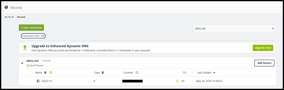
Under “Content” should be the public IPv4 address of the router. Under “Last Update” should be the last time the DDNS was updated. Note that a free hostname must be confirmed every 30 days to keep it. To keep NO-IP up-to-date with the latest public and dynamic IPv4 address of the router, the router can be configured via the router’s configuration page, as shown in Figure 4.

All that needs to be done is entering in the login details for NO-IP, after which a “Success” message should appear at the bottom.
Port Forwarding
To enable port forwarding, go to the router’s firewall settings and look for “Port Forwarding”, as shown in Figure 5.

Select “servers” to set the intended function of the ESP32-C3 station. Under “Name”, enter a name to identify the port to be forwarded. Under “Protocol” select TCP to match the server type, as previously set by the AT+CIPSERVER command. Under “WAN port” and “LAN port”, enter the port number to be forwarded. Under “Destination IP”, enter the IPv4 address of the ESP32-C3 station, as previously set by the AT+CIPSTA command.
Testing the port forward can be achieved using the PortCheckTool as shown in Figure 6.

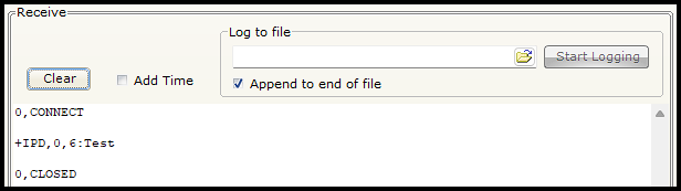
The “Your IP?” field should be automatically filled with the router’s current public IP address. In the “What Port?” field, enter the port number that is port forwarded. Click “Check Your Port”. If a “Success!” message appears, the port is successfully forwarded. In conjunction with this, the receive window of microC Pro for PIC should display messages similar to that shown in Figure 7.

The PortCheckTool establishes a connection with the ESP32-C3, i.e., “0, CONNECT”, after which it immediately disconnects, i.e., “0, CLOSED”.
Remote Communication
Download the SocketTool : TCPUDP & Automation app to remotely send messages to the ESP32-C3.
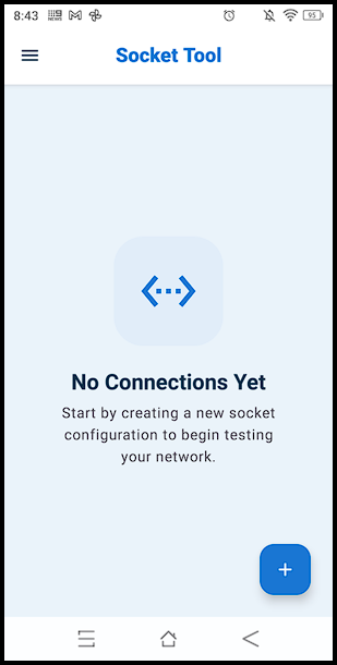
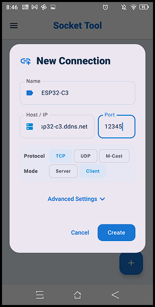
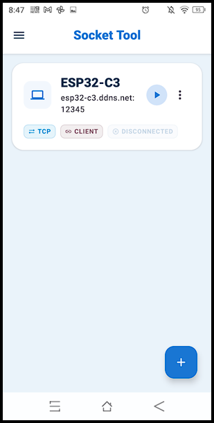
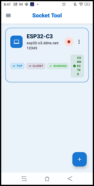
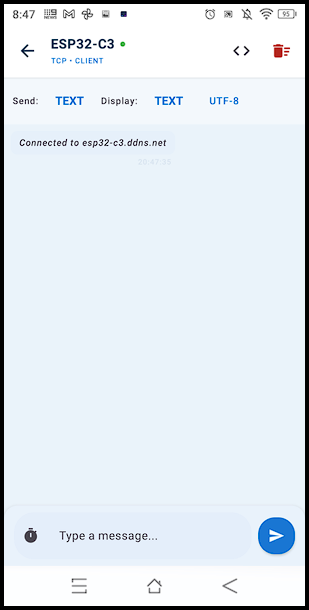
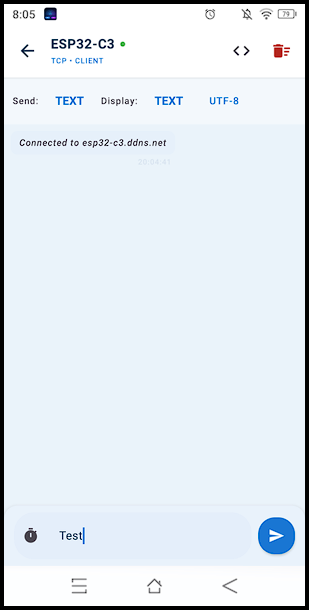
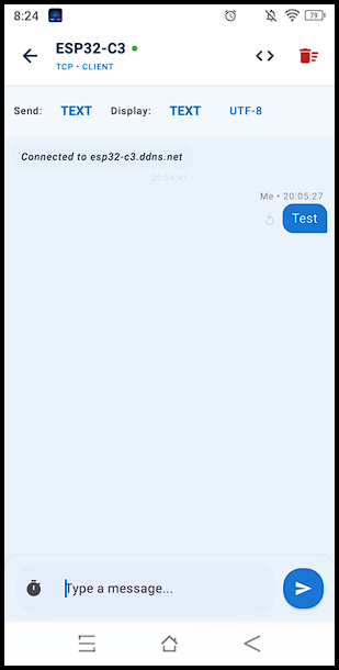
Press the “+” button to create a new connection (Slide 1). Enter the following details: name ESP32-C3, Host/IP esp32-c3.ddns.net, Port 12345, Protocol TCP, and Mode Client (Slide 2). The new connection should be displayed as shown (Slide 3). Press the play button, which should turn into a stop button (Slide 4). Click on the created socket tool to arrive at the messenger screen, which should display the following message: “Connected to esp32-c3.ddns.net” (Slide 5). Type and send a message “Test” (Slides 6-7). Finally, press the stop button to end the connection. In conjunction with these steps, the receive window of microC Pro for PIC should display messages similar to that shown in Figure 8.