Objective
The objective of this laboratory is to demonstrate the nature of the Resistor Capacitor (RC) delay by measuring the charge profile of different valued capacitors.
Preparation
The following schematic details the hardware setup.
Table 1 lists the components used in the schematic.
| ID | Component | Manufacturer Part No. | Value | Qty. |
| R1 & R2 | Resistor | SFR2500001002FR500 | 10 kΩ | 2 |
| C1 | Capacitor (electrolytic) | ESH475M050AC3AA | 4.7 μF | 1 |
| C1 | Capacitor (electrolytic) | ESH476M050AE3AA | 47 μF | 1 |
| C1 | Capacitor (electrolytic) | ESH477M050AL3AA | 470 μF | 1 |
| SW1 | Switch (tactile) | FSM4JART | – | 1 |
Testing
Start by using the 4.7 μF capacitor. Disconnect the red cable from the PSU to disconnect power to the circuit. Press and hold the tactile button for several seconds to ensure that the capacitor is fully discharged. Set the oscilloscope trigger to 200 ms and connect the probe to Test Point 1 (TP1). Connect the red cable to the PSU to connect power to the circuit. Observe the oscilloscope capturing the charge curve of the capacitor. If the curve does not appear cleanly, repeat the above steps and try again. Repeat these steps for the 47 μF and 470 μF capacitors; however, with a 2 s and a 20 s trigger, respectively. Note that to discharge the 470 μF capacitor, the tactile button must be pressed and held down for approximately 20 s. Slides #1 to #3 represent the RC charging curve for a 4.7 μF capacitor, a 47 μF capacitor, and a 470 μF capacitor, respectively.
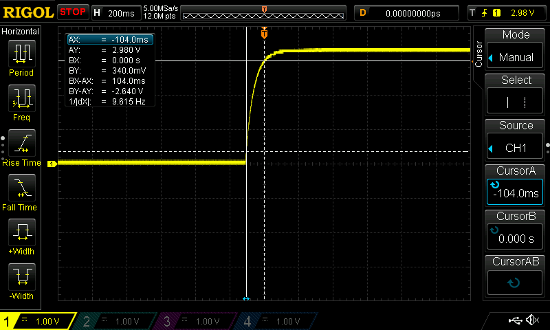
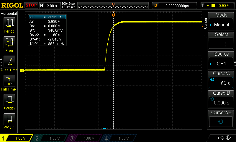
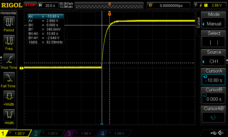
Focusing on Slide #1, the bottom horizontal dotted line represents the 340 mV level, whilst the top horizontal solid line represents the 2.98 V level. The oscilloscope used in this laboratory could not be set at 330 mV and 2.97 V, i.e., 10% and 90%, respectively, of 3.3 V; however, 340 mV and 2.98 V are close enough for representation purposes. The left vertical solid line represents the beginning of the rise time, whilst the right vertical dotted line represents the end of the rise time. The BX-AX represents the rise time of 104 ms. The rise time of the 47 μF capacitor, slide #2, appears to be approximately ten times that of the 4.7 μF capacitor. The rise time of the 470 μF capacitor, slide #3, appears to be approximately ten times that of the 47 μF capacitor.
Conclusion
The RC delay circuit can be utilised for a variety of applications where a delay is required.