It is recommended to first read through the Logic Levels page. Using pull-up/pull-down resistors is essential in managing certain digital communication methods. Certain communication methods, such as a switch-driven input to an input pin of an MCU, do not necessarily require a delicate selection of the value of the pull-up/pull-down resistor. Other communication methods, such as I2C, require a delicate selection of the value of the two pull-up resistors for both SCL and SDA lines and are discussed in the I2C Laboratory. The purpose of pull-up/pull-down resistors is to eliminate issues associated with floating values between LOW and HIGH. Figure 1 demonstrates the “floating” behaviour of an MCU’s input pin that is neither tied to the 3.3 V power rail nor the GND. Moisture in the air and other factors can result in the pin reading random values, i.e., 1s and 0s, which in turn can result in erratic behaviour in a separate circuit that is controlled by the pin’s read value.
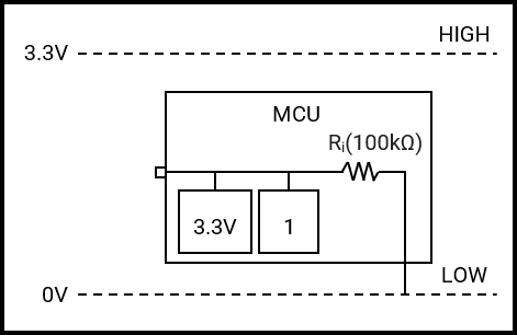
Figure 2 represents the operation of a pull-up resistor (Rp) for a switch-driven input. Circuits utilising a pull-up resistor are typically referred to as Active-LOW, in which a LOW signal initiates communication.

The input impedance (RI) is typically in the order of 100s of kiloohms, similar to that of a multimeter, to take sample voltage readings of an external circuit while causing minimal interference to it by only drawing a very small current. As a general guide, the value of RP can be around one-tenth of the value of RI. When the switch is OFF, RP pulls the input pin up to the 3.3 V power rail, resulting in the MCU reading 3.0 V from the voltage divider RP & RI (Equation 1), which in turn registers as a logic (1). Using Ohm’s law to calculate the current drawn by the pin reveals 30 µA (Equation 2), which is well below the maximum current draw for a typical MCU pin of around 20 mA. When the switch is ON, the input pin of the MCU is directly connected to GND, resulting in the MCU reading 0.0 V, which in turn registers as a logic (0). Using Ohm’s law to calculate the current drawn by RP to GND reveals 330 µA (Equation 3).
\begin{equation}
\tag{1}
\mathrm{V_{(R_I)} = V_H\frac{R_I}{R_P + R_I} = 3.3\frac{100\times10^3}{10\times10^3 + 100\times10^3} = 3\text{\,V}}
\end{equation}
\begin{equation}
\tag{2}
\mathrm{I_{(R_I)} = \frac{V_{(R_I)}}{R_I} =\frac{3}{100\times10^3} = 30 \,\mu\text{A}}
\end{equation}
\begin{equation}
\tag{3}
\mathrm{I_{(R_P)} = \frac{V_{(R_P)}}{R_P} =\frac{3.3}{10\times10^3} = 330\,\mu\text{A}}
\end{equation}
Using a higher value for RP results in a weaker pull-up, resulting in a slower rise time; however, less current is drawn by RP. Using a lower value for RP results in a stronger pull-up, resulting in a faster rise time; however, more current is drawn by RP. A value of 10 kΩ for RP is quite common for a switch-driven input and results in a balance between rise time and power consumption.
Figure 3 represents the operation of a pull-down resistor (RP) for a switch-driven input. Circuits utilising a pull-down resistor are typically referred to as Active-HIGH, in which a HIGH signal initiates communication.

When the switch is OFF, RP pulls the input pin of the MCU down to GND, resulting in the MCU reading of 0.0 V, which registers as LOW. Using Ohm’s law to calculate the current drawn by RP to GND reveals 330 µA. When the switch is ON, the input pin of the MCU is directly connected to the power rail, resulting in the MCU reading 3.3 V, which in turn registers as HIGH. Using Ohm’s law to calculate the current drawn by the pin reveals 33 µA. Using a higher value for RP results in a weaker pull-down, resulting in a slower fall time; however, less current is drawn by RP. Using a lower value for RP results in a stronger pull-down, resulting in a faster fall time; however, more current is drawn by RP. A value of 10 kΩ for RP is quite common for a switch-driven input and results in a balance between fall time and power consumption.