A Microcontroller Unit (MCU) is a “computer” in an ultra-compact package, Integrated Circuit (IC), designed to send data to and receive data from electronic components. An MCU can be found in numerous devices, such as smart lighting, remote controls, white goods, etc. There are numerous types of MCUs, each suitable for specific applications. Figure 1 is an example of some of the many devices that can connect to an MCU.

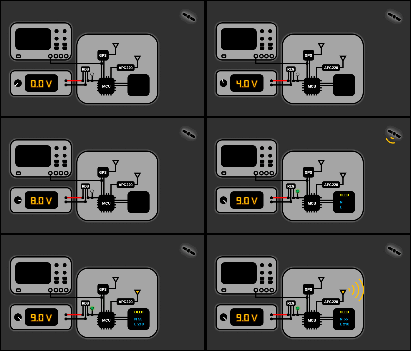
From system-critical devices, such as crystal oscillators, to useful devices, such as display modules, these devices collectively provide an embedded design solution. Figure 2 is an example of a GPS receiver that utilises an MCU.

The GPS module collects spatial data from GPS satellites in space, after which the MCU processes the data and displays characters on the OLED display. The MCU can also share its location with other GPS/MCU systems by transmitting data via a radio module (APC220). Figure 3 is an example of a weather station that also utilises an MCU.

The MCU sends a command to the digital thermometer, as per the thermometer’s manufacturer datasheet, to start taking temperature measurements (1). The digital thermometer then starts taking measurements and converting analog data into digital data to be sent to the MCU for processing (2). The MCU then sends commands to the OLED display, as per the display’s manufacturer datasheet, to display the measured temperature in character format, as per the American Standard Code for Information Interchange (ASCII) standard (3). Trying to couple the digital thermometer directly to the OLED display will not work because such devices are command-driven, i.e., an MCU “middleman” is required. There are many other devices that would be coupled to the MCU to take other measurements such as wind speed and humidity, which can also be represented on the OLED display in character format.
The crystal oscillator is either internal or external and is responsible for setting the timing of the MCU, just like a drum in a marching band, which sets the pace for all band members. This ensures that all internal components of the MCU and external components are functioning in synchronicity. For some MCUs, as per the MCU’s manufacturer data sheet, two clock cycles (from the oscillator) must be generated for one unit/cycle of instruction to be executed by the microprocessor. For example, if the clock cycle of the MCU is 16MHz, the instruction cycle is 8MHz. The program memory holds the software that is uploaded onto the MCU. The Random Access Memory (RAM) supplies instructions to the microprocessor. The Input/Output (I/O) modules provide the MCU with various useful functions such as Analog-to-Digital Converters (ADC), Universal Asynchronous Receiver Transmitter (UART), I2C, Serial Peripheral Interface (SPI), etc.
Table 1 represents common packages for the PIC24FJ256GA702 MCU.
| Acronym | Defenition | Pitch (mm) | Picture |
| SPDIP | Shrink Plastic Dual Inline Package | 2.54 |  |
| SOIC | Small Outline Integrated Circuit | 1.27 |  |
| SSOP | Shrink Small Outline Package | 0.65 |  |
| QFN | Quad Flat No Leads | 0.50/0.65 |  |
| UQFN | Ultra Thin Quad Flat Non-Leaded Package | 0.40/0.50 |  |
The SPDIP is designed for though-hole mounting on PCBs and breadboards, making it the easiest to work with with a relatively large footprint. The SOIC is designed for surface mounting on PCBs, making it relatively easy to work with with a relatively small footprint. The SSOP is designed for surface mounting on PCBs, making it relatively easy to work with with a relatively small footprint. The QFP is designed for surface mounting on PCBs, making it relatively hard to work with with a significantly small footprint. The UQFN is designed for surface mounting on PCBs, making it relatively hard to work with with a significantly small footprint.
Using an MCU development board, such as the Arduino UNO, and other expansion boards, as shown in the centre of Figure 5, is a starting point for learning the basics of microcontrollers.

Setting up the hardware is just a matter of plug-and-play via a USB cable, and setting up the software, i.e., the Integrated Development Environment (IDE), is just a matter of a “few” mouse clicks. The IDE is a platform on which a designer designs software for an MCU. The Arduino IDE can be downloaded from the Arduino website. The onboard hardware includes a programmer, which uploads embedded software from a computer to the MCU. There are several types of Aurdino boards, from tiny boards, such as the Arduino Nano, to large boards, such as the Aurdino MEGA. There are many expansion boards, i.e., shields, that mount onto Aurdino boards to expand functionality, such as a motor control board. This makes prototyping and testing streamlined. This website focuses on PIC MCUs; hence, it is advisable to search other websites for more details regarding the Aurdino platform.
Using an MCU on a breadboard/PCB, such as a Microchip MCU, as shown in Figure 6, involves a steeper learning curve.

Setting up the hardware requires several components, and setting up the software requires configuring several configuration bits. An external programming tool is required to upload embedded software from a computer to the MCU. It is crucial to read through the datasheet for an MCU, paying attention to detail and ensuring that all required components are present, the wiring is correct, the supply voltage is stable and within limits, and any voltages applied to the pins of the MCU are within limits. To establish an MCU testing platform for laboratories and projects, it is recommended to go through the MCUs Laboratory.