An interrupt is a useful feature of an MCU, allowing an urgent instruction to be executed almost immediately, independent of the main program. Interrupts fall into two main categories, either external or internal. External interrupts are a physical pin of an MCU, while internal interrupts are associated with peripherals within an MCU, as shown in Figure 1.

A push-button with a pull-up resistor can be connected to a pin of an MCU, such as INT0 (Pin #16 of the PIC24FJ256GA702), that is capable of serving as an external interrupt. Figure 2 represents an example of a code execution with an Interrupt Service Routine (ISR) to handle the external interrupt (INT0).

When the switch is not pressed, the CPU cycles through all three lines of the Main Code. When the switch is pressed, the Main Code is halted temporarily, and the ISR handler passes an instruction(s) to be executed by the CPU. After the instruction(s) are executed by the CPU, the CPU resumes cycling from Line 2 of the Main Code. Figure 3 represents an example of a code execution with only polling involved.

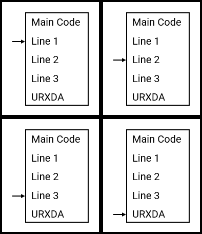
With no ISR used, the CPU will continually cycle through Lines 1 to 3, and the last line, i.e., URXDA. The URXDA line is used to monitor the presence of data in the Receive Buffer of the UART module. If most of the time there is no data in the Receive Buffer, the CPU polls, i.e., checks, URXDA unnecessarily, consuming time and power. If the value of URXDA is crucial and by the time the CPU is ready to process URXDA, it could be too late for the system to respond during a critical situation, such as an emergency shut-down instruction. This is where using an internal ISR specific to the UART receive buffer, i.e., _U1RXInterrupt, solves these issues. Interrupts can be prioritised if there are multiple ISRs involved.