A common communication standard is Universal Asynchronous Receiver Transmission (UART), which can operate in three modes of communication: simplex, half-duplex, and full-duplex, in either a wired or wireless system, as shown in Figure 1.

Simplex communication only involves a transmitter (TX) sending a message to a receiver (RX). An example of simplex communication is a television remote control, which changes channels. Half-duplex communication involves two transmitters/receivers (transceivers), where a message can only be sent from one device to the other in one direction at a time. An example of half-duplex communication is a game of tennis where only one player can hit the ball at a time. Full-duplex communication involves two transceivers where messages can be sent from both devices simultaneously. An example of full-duplex communication is a telephone conversation, where two people can talk simultaneously.
Figures 2 to 4 outline the three main modes of UART communication.

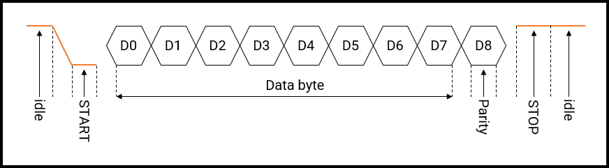
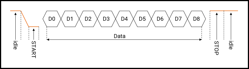
Idle: Before transmission, the communication line on TX is Idle-HIGH, implying that the system is Active-LOW.
START bit: The START bit marks the beginning of communication, where the TX line is pulled LOW.
D0 to D7/D8: Bits D0 to D7, in Figures 2 & 3, and Bits D0 to D8, in Figure 4, represent the 8-bit/9-bit data that is transmitted from the UART’s transmitter module, respectively. The Least Significant Bit (LSB) D0 is transmitted first, whilst the Most Significant Bit (MSB) D7/D8 is transmitted last for 8-bit and 9-bit communication, respectively.
D8: D8, in Figure 3, represents the parity bit, which is optional. The purpose of using a parity bit is for error detection in determining if the character being transmitted is received correctly by a device.
STOP: The STOP bit marks the end of communication, i.e. a bit (1).
Idle: After transmission, the communication line on TX is Idle-HIGH.
Figures 5 and 6 represent the UART transmitter/receiver block of the PIC16F877A MCU, respectively. Refer to pages 115/117 of the datasheet for further details. Note that this 8-bit MCU is used for example purposes only; hence, refer to the datasheet for the PIC MCU being used for specific details.
Figure 5: PIC16F877A Transmitter Block
