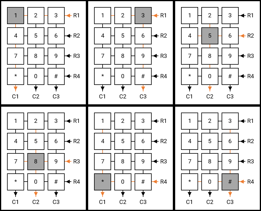
The SP0770 keypad is a device that provides additional functionality by introducing a compact matrix of buttons. Each button can be used to perform a unique task, such as changing the channel on a television.
/*                           Keypad: 3 x 4 (library)                          */
/*                             Filename: Keypad.h                             */
/*                               Author: Michael                              */

void Keypad(void)
{

    Keypad_R1 = 1;                                                              // Set Keypad Row #1 HIGH
    Keypad_R2 = 0;                                                              // Set Keypad Row #2 LOW
    Keypad_R3 = 0;
    Keypad_R4 = 0;

    if (Keypad_C1 == 1)                                                         // If Keypad Column #1 reads HIGH
    {
       // Do something
       while (Keypad_C1 == 1);                                                  // Wait for Keypad [1] to be released
    }

    else if (Keypad_C2 == 1)                                                    // If Keypad Column #2 reads HIGH
    {
        // Do something
        while (Keypad_C2 == 1);                                                 // Wait for Keypad [2] to be released
    }

    else if (Keypad_C3 == 1)                                                    // If Keypad Column #3 reads HIGH
    {
        // Do something
        while (Keypad_C3 == 1);                                                 // Wait for Keypad [3] to be released
    }

    else
    {
        Keypad_R1 = 0;
        Keypad_R2 = 1;
        Keypad_R3 = 0;
        Keypad_R4 = 0;

        if (Keypad_C1 == 1)
        {
           // Do something
           while (Keypad_C1 == 1);                                              // Wait for Keypad [4] to be released
        }

        else if (Keypad_C2 == 1)
        {
            // Do something
            while (Keypad_C2 == 1);                                             // Wait for Keypad [5] to be released
        }

        else if (Keypad_C3 == 1)
        {
            // Do something
            while (Keypad_C3 == 1);                                             // Wait for Keypad [6] to be released
        }

        else
        {

            Keypad_R1 = 0;
            Keypad_R2 = 0;
            Keypad_R3 = 1;
            Keypad_R4 = 0;

            if (Keypad_C1 == 1)
            {
               // Do something
               while (Keypad_C1 == 1);                                          // Wait for Keypad [7] to be released
            }

            else if (Keypad_C2 == 1)
            {
                // Do something
                while (Keypad_C2 == 1);                                         // Wait for Keypad [8] to be released
            }

            else if (Keypad_C3 == 1)
            {
                // Do something
                while (Keypad_C3 == 1);                                         // Wait for Keypad [9] to be released
            }

            else
            {

                Keypad_R1 = 0;
                Keypad_R2 = 0;
                Keypad_R3 = 0;
                Keypad_R4 = 1;
                __delay_ms(100);

                if (Keypad_C1 == 1)
                {
                   // Do something
                   while (Keypad_C1 == 1);                                      // Wait for Keypad [*] to be released
                }

                if (Keypad_C2 == 1)
                {
                    // Do something
                    while (Keypad_C2 == 1);                                     // Wait for Keypad [0] to be released
                }

                else if (Keypad_C3 == 1)
                {
                    // Do something
                    while (Keypad_C3 == 1);                                     // Wait for Keypad [#] to be released
                }

            }

        }

    }

}The SP0770 is a 3×4 (3 columns and 4 rows) keypad, as shown in Figure 1, there are seven terminals, each of which connects to either a column or row.

Columns C1 to C2 can be connected to three pins, configured as read/input (PORT), on an MCU. Rows R1 to R4 can be connected to four pins, configured as write/output (LAT), on an MCU. Pressing Key #1 connects C1 to R1, resulting in the MCU pin, connected to C1, reading HIGH. This is assuming the MCU pin, connected to R1, is at a HIGH state. The MCU pins connected to each of the four rows can be individually set to HIGH in sequence to distinguish which button is pressed. The keypad_R1 word, as shown in the code at line #8, can be defined in the source code as an association with a particular MCU pin and function; for example, #define Keypad_R1 LATBbits.LATB14. The same approach can be applied to all other MCU pins used for the keypad. The following code instructs the MCU to send a HIGH signal on one of the four rows, after which each column is read for a HIGH signal. The “Do something” comment marks the place at which code can be executed to achieve a particular result.